

Micro:Bit Potentiometer LED Brightness Tutorial
Tutorial Aim:
To manually control an LED's brightness using the potentiometer while displaying the LED's power percentage. Where twisting clockwise increases the LED's brightness and counter clockwise decreases the brightness.
Requirements:
This tutorial makes use of the Micro:bit Electronics Learning Package
Pin Layout:
LED Pinout:
| Micro:Bit Pins: | LED Pins: |
| GND | GND |
| 12 | VCC |
Potentiometer Pinout:
| Micro:Bit Pins: | Potentiometer Pins: |
| GND | GND |
| 3.3V | VCC |
| 0 | OUT |
Setup:
Please refer to the diagram below for wiring. Please note that the circuit diagram uses a different Micro:bit shield than the supplied in our package, despite this, the wiring is the same.
- Connect the potentiometer to the Micro:bit by using the FM jumper wires to attach it to pin 0 on the Micro:bit
- Connect the LED to the Micro:bit using FM jumper wires to attach it to pin 12
- Open Microsoft Makecode
- Plug in the Micro:bit to the computer
Note: The LED pin is connected to pin 13 instead of pin 12 in this circuit diagram.

Code Walk Through:
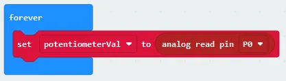
Reading the potentiometer:
We can access how far the potentiometer was turned by reading the signal value at pin 0.
- In the Variables tab, select “make a Variable” and name it “potentiometerVal”. This variable will store the potentiometer reading
- To get the potentiometer reading, in the advanced section in the Pins tab, select “analog read pin (pin number)” and set the pin number to P0
- To set the potentiometerVal to the reading, in the Variable tab, select “set potentiometerVal to (number)” and drag the analog read pin P1 line inside that code snippet
- Place this code snippet inside the ‘Forever’ block as first
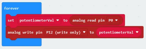
Adjusting the LED brightness:
To adjust the LED brightness based on the potentiometer reading we send a signal to the LED RGB module’s pin.
- In Pins tab found in the Advanced section select “analog write pin (pin number) to (value)”, change the pin number to P12 & set it to the potentiometerVal (found in the Variables tab)
- Place this code snippet inside the ‘Forever’ block
Calculating the light level as a percentage:
We can calculate the light level as a percentage as we know the max value of the potentiometer reading is 1023, and it can be stored in the variable “lightLevel”
- Create a new variable by selecting “Make a Variable” in the Variables tab and name it “lightLevel”
- To calculate the percentage, select the following in the math tab:
- “number / number” & change it to “100 / 1023”
- “number x number” & change it to “potentiometerVal x 100 / 1023” by selecting the variable (found in the Variable tab) and dragging it into the code snippet and also dragging the previous line of code into this code snippet
- “round (number)” & change it to “round potentiometerVal x 100 / 1023” by dragging the math expression into the code snippet
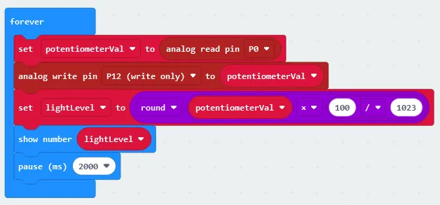
- To set the lightLevel as the percentage, select “set (variable) to (number)” in the Variables tab, change the variable to lightLevel and drag the math expression we created into the code snippet so that it reads “set speed to round potentiometerVal x 100 / 1023”
- To display the speed, select “show number” in the Basics tab, set it to speed & place it inside the ‘Forever’ block lightLevel can be shown on the LED display, by selecting “pause (ms)” in the Basic tab, setting it to 2000 and placing it last in the ‘Forever’ block.
Flashing the code onto the Micro:Bit:
- Make sure the Micro:Bit is connected to the computer
- On the bottom left corner, click the “Download” button and follow the prompts
Block Code:

Python Code:
Simulated LED's Brightness Percent:
Displaying the light level's percentage on the micro:bit's LED grid.
Simulated Potentiometer & LED Brightness
Simulation of how the potentiometer affects the LED's brightness. Please note in this simulation the LED pin is connected to pin 13 instead of pin 12.
Downloadable Content:
Please find this tutorial's python & hex file for microsoft makecode on our Github page.
Credits:
- Microsoft
- The Micro:bit Community
- The STEM Community