

Micro:Bit LED Ring Speed Tutorial
Tutorial Aim:
The aim of this tutorial is to control the rotation speed of the LED ring on the KittenBot RobotBit by increasing or decreasing it when either of the switch buttons is pressed.
Pin Layout:
The pinouts of the momentary buttons to control the RGB module are as shown below:
Bit RGB LED Module Pinout:
| Micro:Bit Pins: | RGB LED Module Pins: |
| GND | GND |
| 3.3V | VCC |
| 15 | IN |
Speed Increase Button Switch Pinout:
| Micro:Bit Pins: | Button Switch Pins: |
| GND | GND |
| 0 | VCC |
Speed Decrease Button Switch Pinout:
| Micro:Bit Pins: | Button Switch Pins: |
| GND | GND |
| 1 | VCC |
Setup:
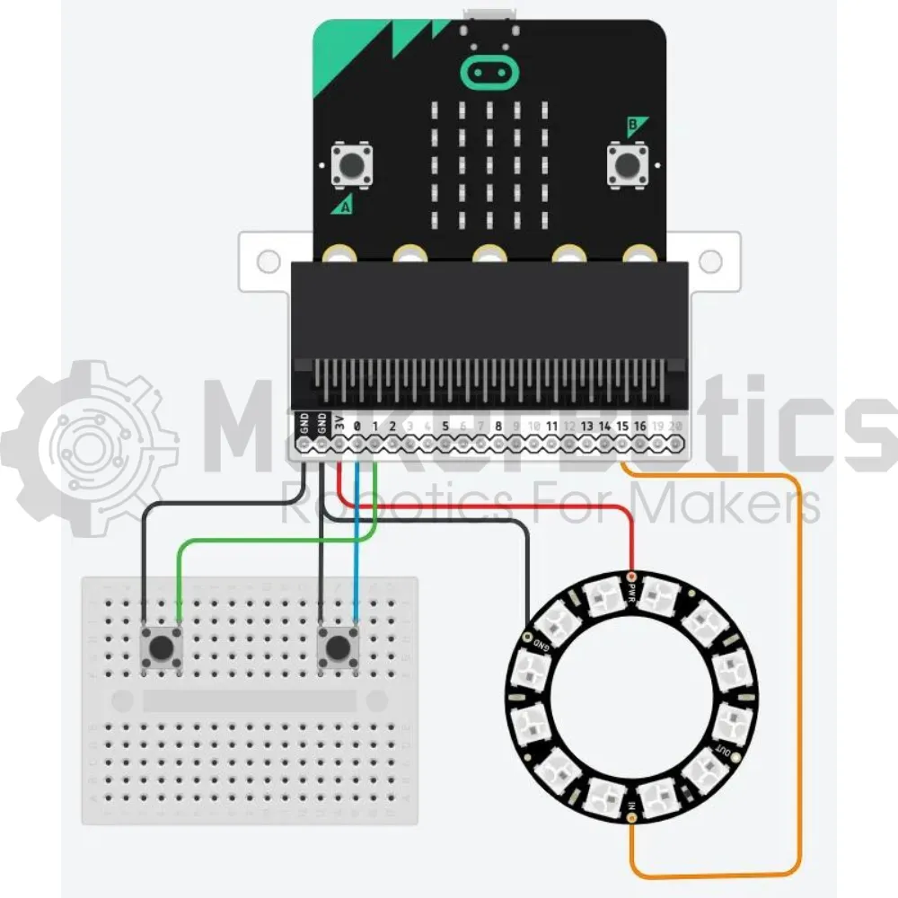
Please refer to the diagram below for wiring. Please note that the circuit diagram uses a different Micro:bit shield than the supplied in our package, despite this, the wiring is the same.
- Connect the button switches to pin 0 & pin 1 on the micro:bit using the FM jumper wires.
- Connect the LED ring to the Micro:bit using the crocodile clips to attach it to pin 15
- Open Microsoft Makecode
- Plug in the Micro:bit to the computer
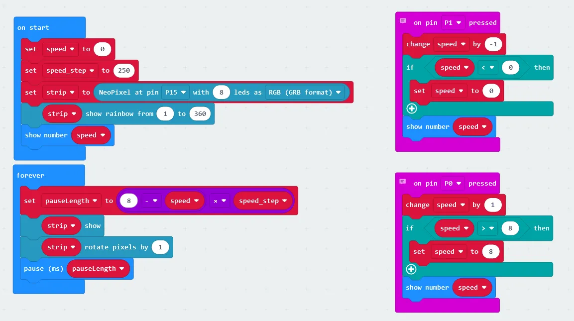
Code Walk Through:
Initializing variables, switches and led ring:
We can control the speed of the led colour rotation by determining how long each colour is displayed; short duration = fast speed & long duration = slow speed. To store the current speed level and how much to increase/decrease the speed by, we create the variables “speed” & “speed_step” respectively. Speed step is calculated by: The max duration each colour can be shown before the next rotation (2000ms or 2 seconds) ÷ number of levels (8) = 250 . The code for this section will go inside the "on start" block
For more information about the extension https://makecode.microbit.org/pkg/kittenbot/pxt-robotbit
- Creating & setting a variable for the speed increase: In the Variables tab, select “Make a Variable” & name it “speed_step”. Then select “set speed_step to (number)” and set it to 250
- Creating a variable to store the speed: Create a new variable names “speed” & set it to 0
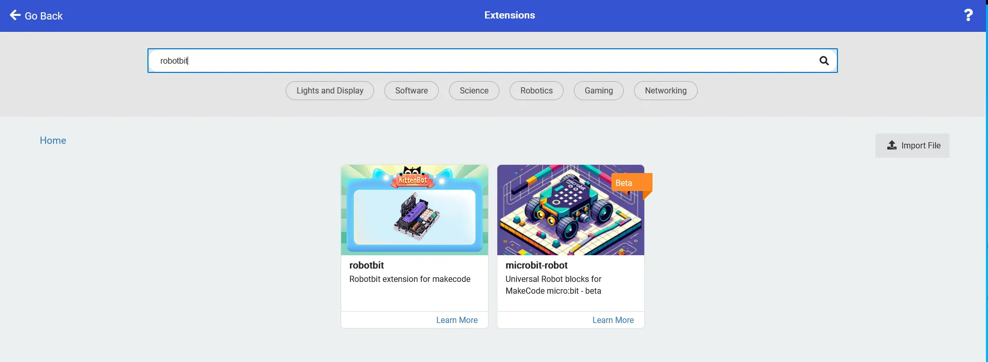
- Adding in the extension: In the extensions tab, search & select the robotbit extension by kittenbot
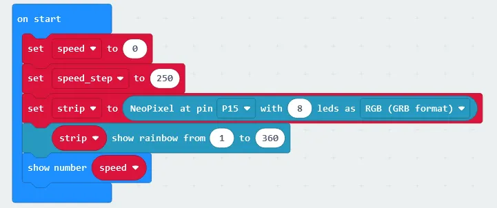
- Initializing the led strip: In the Neopixel tab, select “set strip to NeoPixel at P0 with 24 leds as RGB format” & change P0 to P15 and 24 leds to 8 leds
- Calibrating the led colours & formation: In the Neopixel tab select “strip show rainbow from 1 to 360” and place the code snippet in the “on start” block
- Displaying the speed: In the basic Tab, select “show number (number)” and change it to “show number speed”, where “speed” can be found in the Variables tab, and place this code snippet last in the “on start” block
Increasing the speed when the button attached to pin 0 is pressed:
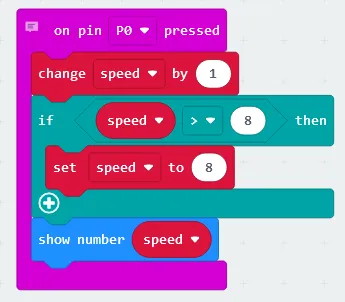
When the increase speed button is pressed, we need to check that if the current speed level is already the max level we keep the speed as is (which is the max speed level), otherwise we increase the speed by one level. The code for this section will go inside the “on pin P0 pressed” block
- Creating an event handler: In the Input tab select “on pin P0 pressed”
- Increasing the speed: In the Variables tab select “change speed by 1” and place the code inside the “on pin P0 pressed” block
- Creating the conditional block: In the Logic tab select the if conditional block
- Checking if the speed is already at max: In the Logic tab select the comparison “0 > 0” line, change it to “speed > 8” & place the code inside the if statement.
- Keeping the speed the same if it’s already at max: In the Variables tab select “set (variable name) to (number)” & change it to “set speed to 8” before placing the code inside the conditional block.
- Displaying the current speed: In the Basic tab select “show number (number)” & change it to “show number speed”, where “speed” can be found in the Variables tab. Place this line of code at the end of the “in pin P0 pressed” block
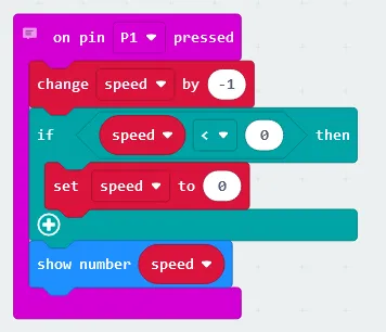
Decreasing the speed when the button attached to pin 1 is pressed:
Decreasing the speed is similar to increasing the speed except we now check to see if the speed is > 0. The code for this section will go inside the “on pin P0 pressed” block
- Creating an event handler: In the Input tab select “on pin P1 pressed”
- Decreasing the speed: In the Variables tab select “change speed by -1” and place the code inside the “on pin P0 pressed” block
- Creating the conditional block: In the Logic tab select the if conditional block
- Checking if the speed is already at min: In the Logic tab select the comparison “0 < 0” line, change it to “speed < 0” & place the code inside the if statement.
- Keeping the speed the same if it’s already at min: In the Variables tab select “set (variable name) to (number)” & change it to “set speed to 0” before placing the code inside the conditional block.
- Displaying the current speed: In the Basic tab select “show number (number)” & change it to “show number speed”, where “speed” can be found in the Variables tab. Place this line of code at the end of the “in pin P1 pressed” block
Note: The blocks of “on pin x pressed” will only run when the button attached to pin x is pressed
Updating the LED ring:
The amount of time each LED colour is displayed (pauseLength) is calculated by the amount of levels - the current speed x the speed step, where the longest display time length is 2000 ms / 2 seconds, and the shortest is 250 ms. The code for this section will go inside the ‘forever’ block.
- Creating “pauseLength”: In the Variables tab select “Make a Variable” & name it ‘pauseLength’
- Calculating how long each colour is shown: In the math tab select-
- “0 - 0” & change to “8 - speed”
- “0 x 0” & change to “8 - speed x speed_step” by dragging the previous line inside this code
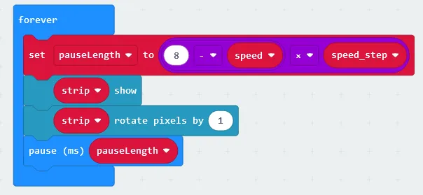
- Setting pauseLength to the calculation: In the Variables tab select “set (variable name) to (number) & change it to “set pauseLength to 8 - speed x speed_step”
- Displaying the colours on the LED strip: Select the “strip show” line in the Neopixel tab
- Updating the colour formation: Select “strip rotate pixels by 1” in the Neopixel tab
- Pausing the loop for a specific duration: Select the line “pause (ms)” in the Basic tab & change it to “pause (ms) pauseLength” before placing the code snippet last inside the forever block
Flashing the code onto the Micro:Bit:
- Make sure the Micro:Bit is connected to the computer
- On the bottom left corner, click the “Download” button and follow the prompts
Block Code:
Python Code:
Simulated Speed Level:
Increasing & decreasing the speeds by interacting with pin 0 & pin 1
Simulated Ring Speeds:
Displaying the speed differences of each level.
Downloadable Content:
Please find this tutorial's python & hex file for microsoft makecode on our Github.
Credits:
- Microsoft
- The Micro:bit Community
- The STEM Community