

Interfacing A02YYUW-1AT Ultrasonic Sensor With Arduino Uno
Introduction
The goal of this project is to seamlessly interface the A02YYUW sensor with an Arduino to capture and display sensor data in real-time using the Arduino’s Serial Monitor. By the end of this project, you will have a clear understanding of how to connect the sensor to the Arduino, write the necessary code to read sensor data, and utilize the Serial Monitor to visualize the data. This project is perfect for beginners looking to enhance their skills in sensor integration and data visualization with Arduino.
Materials:
About The A02YYUW Ultrasonic Sensor
The A02YYUW sensor is an ultrasonic sensor used for measuring distance with high precision. It emits ultrasonic waves and calculates the time it takes for the waves to bounce back from an object, providing accurate distance measurements. This sensor is commonly used in various applications such as obstacle avoidance in robotics and distance measurement in automation systems.
Note: There are different variants of the A02YYUW sensor, utilising different communication protocols. This variant is the UART Controlled Type.
Pin Layout
The A02YYUW sensor comes with a JST connector with colour-coded wires. The pin layout for each pin is displayed below:

Power Connections:
Wire pin (1) VCC from the JST connector to 5V on the Arduino. Next, connect pin (2) GND from the JST connector to GND on the Arduino.
Communication:
Connect Pin 3 RX from the JST Connector to pin 3 on the Arduino and connect Pin 4 TX to pin 2 on the Arduino.
See the wiring diagram below:

Code
Initialisation:
Define the pins output and inputs, then begin the serial.
Main loop:
Reset the RX pin. Then, detect the pulse. The RX pin is then set to high again so that the measurement can be taken. The data is then read in serial format. Lastly, display the distance in centimeters in the Arduino IDE.
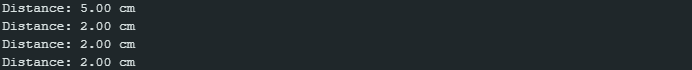
Console Output:
You should see the distance measured by the sensor displayed into the Arduino IDE Serial Monitor, like the following.
Downloadable Content
Please find this tutorial’s code on our GitHub page.
Credits:
- Maker Community
- The Arduino Community
- The STEM Community