

Interfacing A Dual Shaft Serial Bus Servo With A Teensy 4.0
Tutorial Aim:
In this tutorial, we will interface a Teensy microcontroller to fully rotate a dual shaft serial bus servo using a FE-URT-1 board and CH340 driver. Extending from this, we can daisy chain the servo's and fully rotate them independently.
Introduction:
The STS3020 serial bus servo is a high-performance servo motor designed for precision control in various applications. With a torque of 20kg and an operational angle of 360 degrees, this servo is extremely versatile and can be used in a wide range of advanced applications. Due to the advancement of software in robotics, Serial bus servos are fast becoming the go-to servo for automation applications.
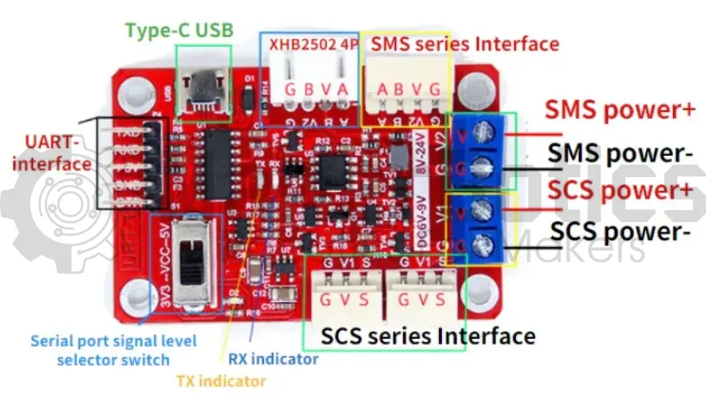
The FE-URT-1 controller is a multifunction device, used to debug and control the STS and SCS series of servos via the serial interface. This controller can be used to control serial bus servos for use in projects such as robot arms, pan-tilt systems or bipedal robots to name a few.
Key Concepts:
- Serial Bus Servo: Communicate using serial communication (RX/TX pins), multiple serial bus servos can be connected to the same communications port of the host microcontroller which requires only two pins, saving GPIO pins.
- Serial Bus Servo Feedback: Allow for telemetry, giving you feedback on the servo position, current, voltage and current output, expanding the control capability of the servos.
- Daisy Chaining The Servos:Multiple serial bus servos can be connected to the FE-URT-1, making it easy to interface and communicate with only two wires as serial bus servos can be daisy-chained.
Please note, this tutorial continues from the "Getting Started With Teensy And The Arduino IDE" tutorial and the "Controlling A Dual Shaft Serial Bus Servo" tutorial.
Pin Layout:
| FE-URT-1 Pin | Teensy Pin |
| GND | GND |
| RX | 7 |
| TX | 8 |
| FE-URT-1 SCS Series Interface Pin | Dual Shaft Serial Bus Servo Pin |
| G | G |
| V | V |
| S | S |
Setup:
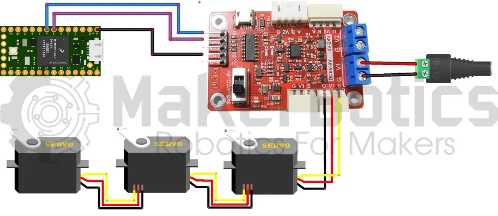
Please refer to image below for wiring. Please note that the circuit diagram is for daisy chained servos. The same wiring is used for a single servo.
- Connect the fe-urt-1 board to an external power supply & attach the STS3020 servo.
- Connect the fe-urt-1 board to the teensy 4.0 pins using the FM jumper wires.
- Open Arduino IDE
- Plug in the Teensy to the computer
Code Walk Through:
Controlling A Single Servo:
Libraries:
We use the imported library SCServo.h from FTServo to access & control the servos. Please refer to the Arduino Docs page on how to import a library from a zip file. We'll also define the servo's ID for easier access.
For information about the SCServo.h library by FTServo please visit their Gitee page.
Initializing The Servo:
The servo uses a serial port for communication. As Serial is used for the Serial Monitor, we'll be using Serial2 via pin 7 & pin 8, and initializing the servo to Serial2.
Forward & Backward Full Rotation:
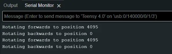
To rotate the servo we specify which servo to be rotated by ID, and input the position, speed & acceleration. We assume that the servo is at position 0 (P0 = 0) and rotate it fully (P1 = 4095), then rotate it backwards to the starting position.
Serial Monitor Output:
The servo's rotation is displayed on the serial monitor for clarity & debugging purposes.
Controlling Daisy Chained Servos:
We can extend from the single rotation tutorial, to rotate daisy chained servo's individually.
Pin Layout:
| FE-URT-1 DC 6V - 9V Pin | External Power Supply |
| G | GND |
| V1 | VCC |
| Dual Shaft Serial Bus Servo Pin | Dual Shaft Serial Bus Servo Pin |
| G | G |
| V | V |
| S | S |
Setup:
Please refer to the circuit diagram above.
- Connect the fe-urt-1 board to an external power supply & attach the servo.
- Connect the remaining servo's to each other so that they form a daisy chain.
- Connect the fe-urt-1 board to the teensy 4.0 pins using the FM jumper wires.
- Open Arduino IDE
- Plug in the Teensy to the computer
Code Walk Through:
Library & Servo IDs:
As an extension of the tutorial, we can also control daisy chained servos using the same library as before & defining the servo's IDs.
Please note that the servo's used have unique ID's. If any of the servo's share IDs then those servo's will move at the same time. To change your servo's ID's please follow our "Controlling A Dual Shaft Serial Bus Servo" Tutorial. <-- INCLUDE LINK WHEN TUTORIAL IS PUBLISHED
Initializing The Servos:
We initialize the servo's the same as before.
Rotating A Given Servo:
For simplicity, we create a function that'll fully rotate the servo with the given ID.
Rotating All Servos:
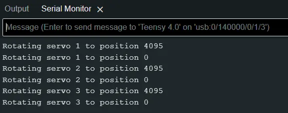
We'll continuously batch rotate all the servos every 3 seconds.
Serial Monitor Output:
Each servo's rotation is displayed on the serial monitor for clarity & debugging purposes.
Single Servo Rotation Code:
Daisy Chained Servos Code:
Downloadable Content:
Please find this tutorial's python & hex file for microsoft makecode on our GitHub page.
Credits:
- Feetech
- The Maker Community
- The STEM Community