

Interfacing a BME680 sensor and 2004 LCD with an RP2040 Controller
Introduction
This tutorial will go through the steps taken to interface a BME680 sensor and a 2004 LCD with a Raspberry Pi Pico variant model, using MicroPython. Interfacing these two components will allow the environmental data collected by the BME680 sensor to be displayed onto the 2004 LCD screen. Once this project is complete, you will have gained experience with wiring and have greater familiarity with the RP2040 core board (Raspberry Pi Pico). This is a great project for those looking to work with the RP2040 board and code microcontrollers using MicroPython.
Materials:
- PC with Thonny installed
- RP2040 core board (Raspberry Pi Pico)
- BME680 sensor
- 2004 LCD display module
- Breadboard
- Jumper cables
- USB-A to USB-C cable
Pin Layout for the BME680 sensor
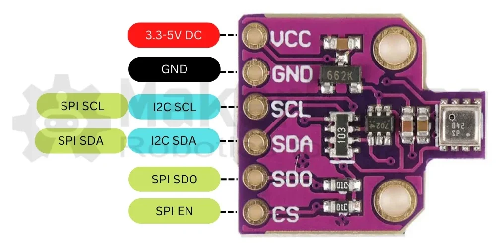
Power Connections:
Wire the VCC pin to the 3V3 pin of the Raspberry Pi Pico. Then connect the GND pin to one of the available GND pins on the Raspberry Pi Pico.
Communication:
Wire the I2C SDA pin to GP14 and the I2C SCL pin to GP15 of the Raspberry Pi Pico.
About the 2004 LCD screen
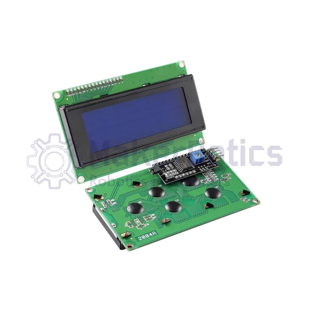
The LCD 2004, also known as the 2004character-type liquid crystal display, is a dot matrix module designed to showcase letters, numbers, and characters. Its model number, 2004, signifies its capacity to display 4 lines of 20 characters.
The 2004 LCD screen traditionally uses the SPI communication protocol, but the variant used for this project can use I2C, reducing the number of pins that need to be used.
Pin Layout for the 2004 LCD display module
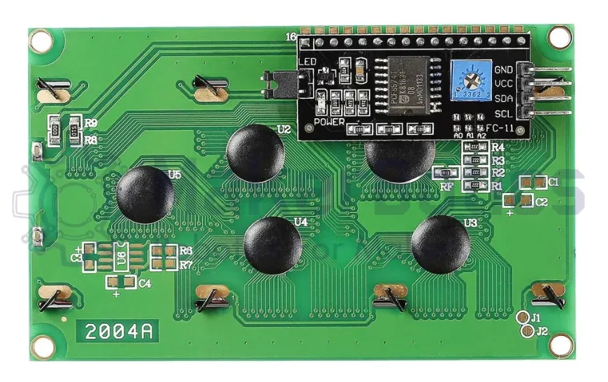
Power Connections:
Wire the VCC pin to the Vout pin of the Raspberry Pi Pico. Then connect the GND pin to one of the available GND pins on the Raspberry Pi Pico.
Communication:
Wire the I2C SCA pin to GP4 and the I2C SDL pin to GP5 of the Raspberry Pi Pico.
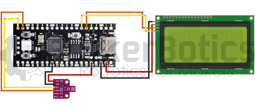
Wiring and Setup
Both the BME680 and the 2004A LCD use the I2C communication protocol, but the GPIO pins can be configured according to preference. In the code provided with this tutorial, the SDA and SCL pins of the LCD module and the BME680 sensor have been explicitly assigned.
The wiring diagram for this project is as follows:
Libraries
BME680 Library
https://github.com/robert-hh/BME680-Micropython/blob/master/bme680.py You can download the library used for the BME680 sensor by navigating to this website: https://github.com/robert-hh/BME680-Micropython/blob/master/bme680.py . You should then save the python file ‘bme680.py’ onto the Raspberry Pi Pico by taking the following steps:
- Open the downloaded python file ‘bme680.py’ with Thonny
- Make sure the interpreter selected in Thonny is the Raspberry Pi Pico
- Afterwards, save the file onto the Raspberry Pi Pico. You should see this small window pop up:
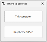
- Save the file in the directory ‘Raspberry Pi Pico/lib’
Saving the python file onto the ‘lib’ file of the Raspberry Pi Pico board adds the ‘bme680.py’ file as a file to be used as a part of the Raspberry Pi Pico’s library.
LCD_I2C Library
To obtain the library used to operate the LCD using I2C:
On your browser, open the following link: https://pypi.org/project/micropython-i2c-lcd/#upload-files-to-board
Next, download the file, it is a .tar.gz file. Open the lcd_i2c file inside, and open all the .py files using Thonny. Using Thonny, create a new directory in the ‘lib’ file of the Raspberry Pi Pico and name it ‘lcd_i2c’, and save all the .py files of the lcd_i2c file on your PC there. You have essentially added the MicroPython I2C LCD library to the Pico board you are using. If you open the file called ‘lcd_i2c.py’ from the ‘lcd_i2c’ file in the Raspberry Pi Pico, you can view the class called LCD, its properties and functions, all of which you can use once importing the LCD class.
Code
After adding both libraries to your Raspberry Pi Pico board, type out the following code onto a new script:
End Result
Running this code should display some text and the temperature that is currently being read by the BME680 sensor, onto the 2004 LCD display module. The pictures/video below shows the text and temperature being displayed on the screen as expected.
Downloadable Content
Please find the code for this tutorial on our GitHub page.
Credits
- Maker Community
- The Raspberry Pi Community
- The STEM Community