

Getting Started with the ESP8266 and the Arduino IDE
Introduction
This Getting Started with the ESP8266 and the Arduino IDE guide aims to guide you on how to set up the ESP8266 microcontroller with the Arduino IDE.
ESP8266-based microcontrollers such as the NodeMCU V2 are supported.
Requirements:
Step 1: Download the Arduino IDE and ESP8266 Drivers
- Visit the Arduino website to download the Arduino IDE version 2.x.x. Note that all versions from 2.0.4 onwards are compatible, but it is recommended to use version 2.3.0 or later for enhanced features in the Boards Manager.

Driver Installation
USB drivers are required for your ESP8266 chips to communicate with your computer. The two most common chips are the CH340G and the CP2102. Verify ith your vendor which USB driver your ESP8266 has.
The NodeMCU V2 used in this example requires the CP2102 USB driver.
Step 2: Install The ESP8266 Boards on Arduino IDE 2.x
- Open the Arduino IDE.
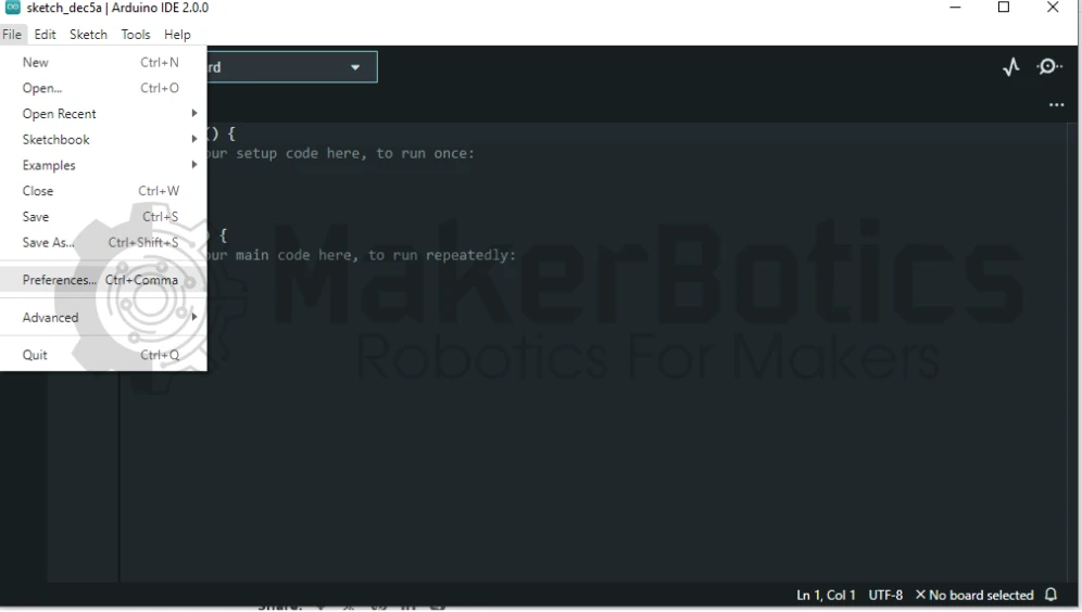
- For Windows/Linux: Navigate to File > Preferences.
- For MacOS: Go to Arduino IDE > Settings.
- In the “Additional boards manager URLs” field, add the following link.
If you already have other URLs added, simply add a comma after the last URL and paste this URL as shown below by the orange arrow. Click Ok

You will now notice that the board data will start to download.
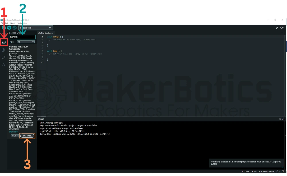
Next, we will install the boards. To do this, navigate to the board manager icon highlighted by the red square [1]. Clicking it will open the board manager search bar. In the search bar highlighted by the blue rectangle [2] type in ‘ESP8266’.
The board list will show, click on the Install button highlighted by the orange rectangle [3]. The boards will now install and the progress can be monitored in the output bar.
3. Verify and Test Board Install
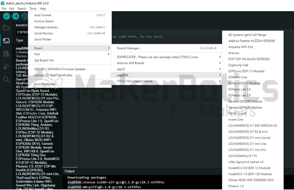
After installing the board, we will test the installation, firstly check that the boards have been included in the board manager board list as shown below.
After checking, copy and paste the code below to test the board with an LED blink sketch by blinking the built-in LED.
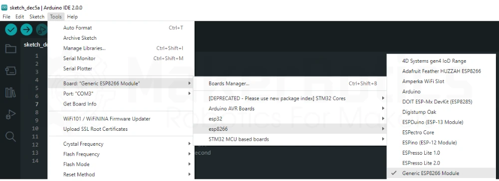
Connect your NodeMCU V2 and select the board as Generic ESP8266. Double-check the COM Port number in Device Manager.
After uploading the code, you will notice the Built-in LED Blinking.

Credits
- Maker Community
- The ESP8266 Community
- The STEM Community