

An Introduction To Serial Bus Servos
Tutorial Aim:
In this tutorial, we'll use Feetech software to control different dual shaft serial bus servo's using a FE-URT-1 Serial Bus Servo Controller. We'll display how to change servo ID's & how to control multiple servo's.
Introduction:
Serial bus servos are advanced servos that communicate via the serial protocol rather than the standard PWM protocol.
This allows for sending back important data such as telemetry, giving you feedback on the servo position, current, voltage and current output, expanding the control capability of the servos. As serial bus servos communicate using serial communication, multiple serial bus servos can be connected to the same communications port of the host microcontroller which requires only two pins, saving GPIO pins. To control these servos, a serial bus servo controller is required.
The FE-URT-1 Serial Bus Servo Controller is a multifunction device, used to debug and control the STS and SCS series of servos via the serial interface. This controller can be used to control serial bus servos for use in projects such as robot arms, pan-tilt systems or bipedal robots to name a few.
Key Concepts:
- Feetech Software: This software facilitates servo parameter changes, access to the servo's position, torque, speed, current, temperature & voltage, with graphical representation & analysis.
- Serial Bus Servo Feedback: This is the telemetry data, giving you feedback on the servo position, current, voltage and current output, expanding the control capability of the servos.
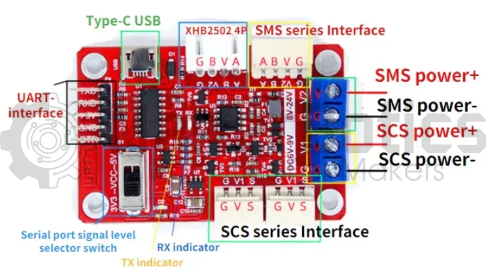
Pin Layout:
| FE-URT-1 DC 6V - 9V Pin | External Power Supply |
| G | GND |
| V1 | VCC |
| FE-URT-1 SCS Series Interface Pin | STS3020 / SCS225 Servo |
| G | G |
| V | V |
| S | S |
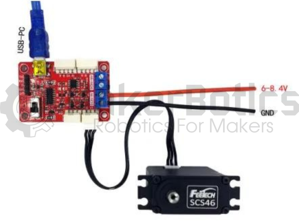
Setup:
Please refer to image below for wiring.
- Connect the fe-urt-1 board to an external power supply & attach the STS3020 servo.
- Plug in the Teensy 4.1 to the computer
Software Walk Through:
Software:
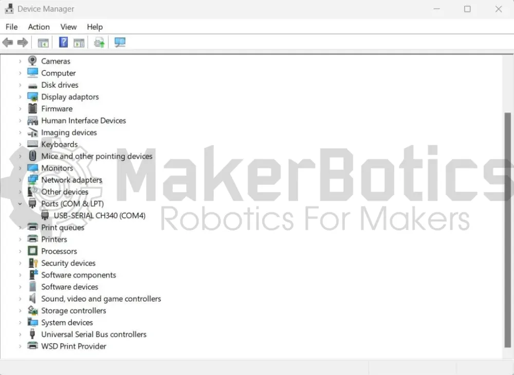
In order for us to control each servo individually, we'll need to set each servo to have a unique id. Updating each servo must be done one at a time, so only one servo can be connected to the fe-urt-1 board. We can change the servo's parameters using the feetech software. Connect one servo to the fe-urt-1 board as displayed in the image below and open device manager. Take note of which port the driver is using, in this example its COM4.
If multiple servo's are connected & share the same ID, then the feetech software will only display one of the servo's & not all of them. Furthermore, we won't be able to access each distinct servo as servos are controlled using their ID's, so any command to a particular ID will influence all the servo's attached.
Please note, that this tutorial assumes that the CH340 driver has already been installed. For information about how to use the feetech software please visit feetech's user guide.
Changing the Com Settings:
Open the feetech software and next to "Com" use the dropdown box to select the servo's port. Change the baud rate to 1000000 for the SCS / STS series servos, and 115200 if you are using the SMS series.
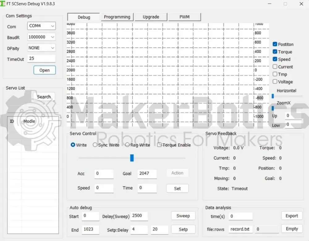
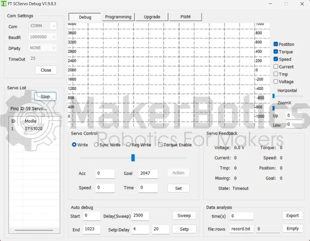
Searching For The Servo:
Once the "Com Settings" have been adjusted according to the servo, click "Open" & then "Search". Once the connected servo appears with its current ID, stop the search & select that servo. As you can see in the image below, we're updating the STS3020 servo with and ID of 1, but it can be any compatible servo.
Please note that the servo will not appear if the baud rate is incorrect or there's no power supply.
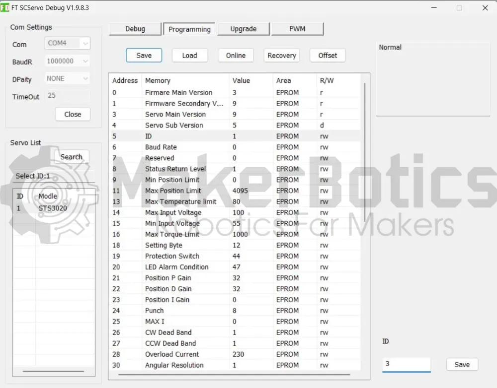
Changing The Servo ID:
Navigate to the "Programming" section and select address 5, memory ID line. In the bottom right corner, change the value of ID to a unique numerical value not shared with the other servo's you'll be using. For this example, our current ID is 1 & we'll be changing it to 3.
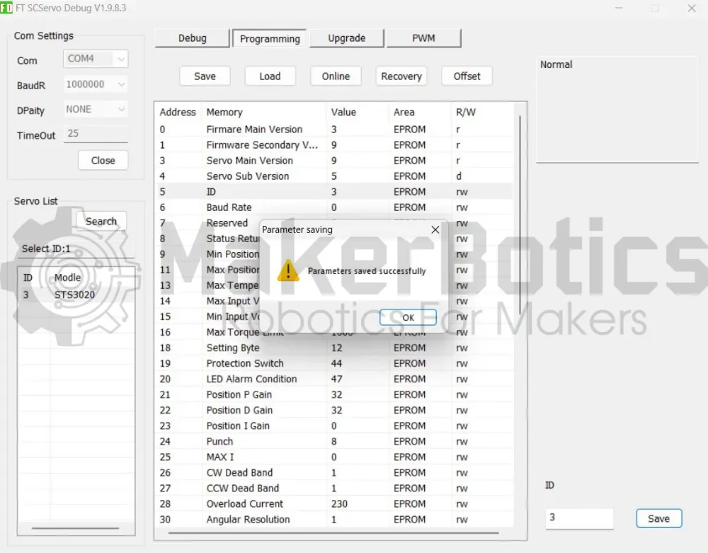
Updating The Servo ID:
Update the servo's ID and press save. The program should output a successful parameter saved message & the ID under the "Select ID: " section should be updated with the new value.
Please repeat the previous steps for each servo used so that every servo has a different ID value.
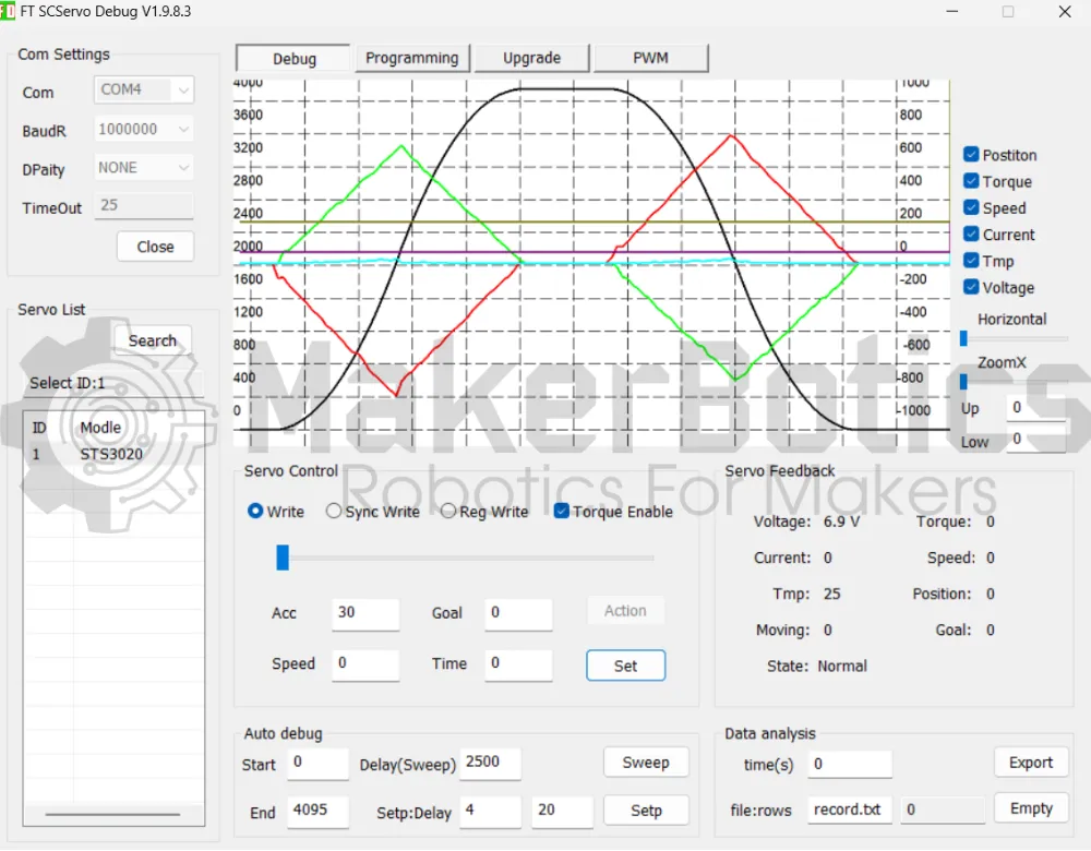
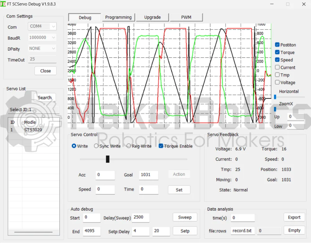
Moving The Servo Using Input:
We can control the acceleration, speed, position & time of the servo movement in the Debug tab, under "Servo Control". For a full rotation input the following values & select set:
- Acc = 30
- Goal = 4095
The graph will plot the selected servo's values against time.
Moving The Servo Using The Slider:
We can control the servo's acceleration, speed & position user the slider bar provided under "Servo Control" by how quickly and how far the bar is moved.
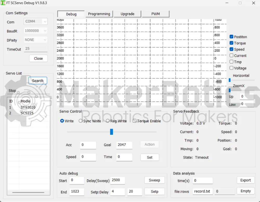
Daisy Chained Servos:
Accessing Daisy Chained Servos:
The process of controlling daisy chained servo's is the same as controlling one servo given the servo's have different ID's. When searching for the servos, all the servos with different ID's should appear. To access a particular servo, you select it from the "Servo List" and continue as before.
Simulated Servo Input:
The video below shows the screen capture of real time servo telemetry output when it is manually activated in the software.
Simulated Slider Servo Input:
Simulated Daisy Chained Servos:
Multiple servos can be added and controlled as shown below.
Credits:
- Feetech
- The Maker Community
- The STEM Community