Blogs
Create Pinout Diagrams That Impress with Python
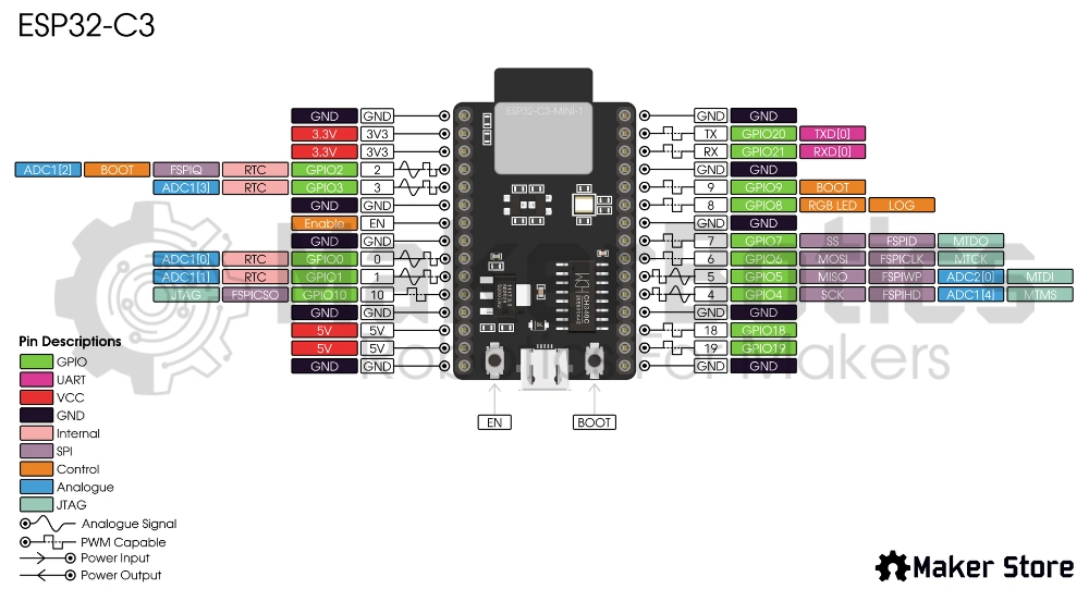
Have you been wondering how you can level up your project’s diagrams and documentation? Maker Store has recently unveiled pinout diagrams for all microcontrollers and motor drivers on its store. To give you an insight into the design process, this blog aims to give you the essentials. To give your project the look of professionalism that you desire. While we will focus on pinout diagrams today, some of the information can be applied to a whole range of applications. In this blog, we will create a pinout diagram for an ESP32-C3. We will be using a CSV (Comma-Separated Value) file, which contains all the descriptions for each pin. This CSV file is then opened in a Python program and automatically converted to an SVG (Scalable Vector Graphics) file. From here, we can use Inkscape, a free image editing program, to finalise the diagram’s design.
This tutorial uses code based on the Graphical Datasheets program by Sparkfun: https://github.com/sparkfun/Graphical_Datasheets
What you'll need
- Python 3.12
- Svgwrite 1.4.3
- Pinout Generator Program
- Inkscape
- Microsoft Excel (or Google Sheets)
Making a CSV file
The first step is to create a CSV file for your microcontroller (or anything else that you want to label). We recommend using the example file, ESP32-C3.csv, as a template. Click Here to Download Example File
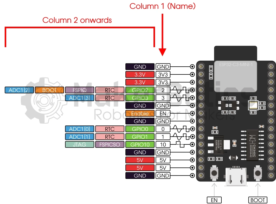
You can edit these files using Excel. The file’s first column, Name, is what the pin will be called in the diagram. Each column thereafter can then be written in, which will assign a pin description in that category
Running the program
Using a program is a fast way to make your diagrams consistently look good. The program used in this blog is written in a language called Python. Python is easy to learn, yet has a large variety of applications.
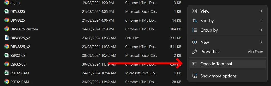
1. Locate the root of /Pinout Generator/, right click and select ‘Open in Terminal’
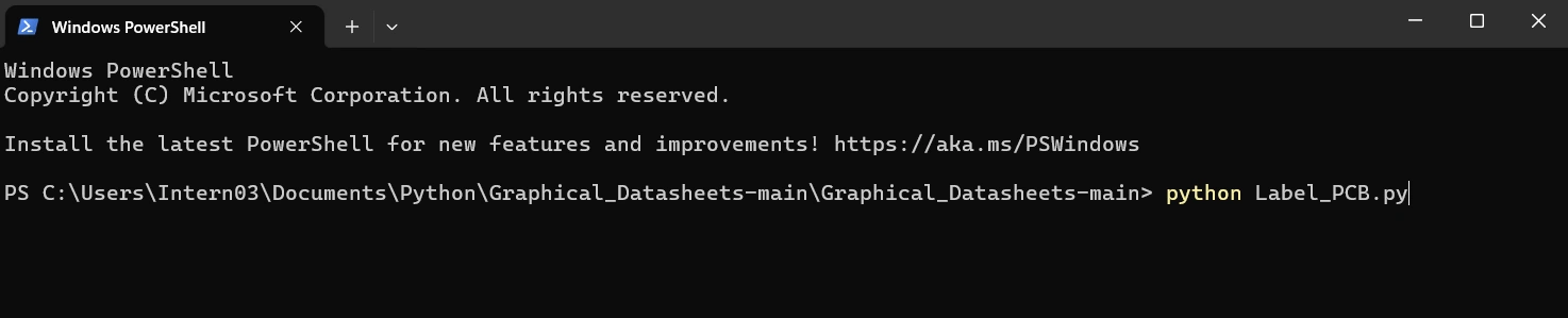
2. Type in the following command in the terminal to run the label program for a microcontroller: python Label_PCB.py. Alternatively, the following command can be used for motor drivers or other smaller hardware: python Label_Motor.py. Press enter.
3. Enter in the name of the CSV file you want to generate a diagram for (without the .csv file extension). Press enter.
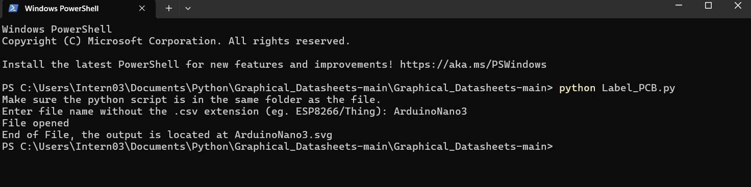
If you see the message ‘End of File, the output is located at [filename].svg, then congratulations! You have generated your first pinout diagram. The format should look similar to the following:
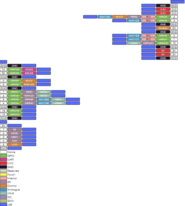
Finish up your Pinout diagram
Now that you’ve generated your labels, it’s time to make the diagram look pretty! Let’s clean it up in a program such as Inkscape. Firstly, delete any unnecessary labels and adjust your font size. Next, insert your microcontroller. We can then rearrange the labels so that they align with it.
Designing pin connectors is a great way to enhance your diagram. These icons connect the labels to your PCB in an intuitive way. By combining basic shapes and line art using the pen tool, you can create your own pin connector style too.
Lastly, its time to add any other information you may need. This may include titles, legends, or credits.
Nice work! You were able to successfully create your first pinout diagram.
Credits
- Sparkfun, for their Graphical Datasheets program that this tutorial is base on.
- The Maker Community
- The STEM Community