

Interfacing the NoESP8266 Addressable WS2812 Neopixel Rings
Introduction
In this project, the addressable WS2812B LED ringmodule will be interfaced with the ESP8266 NodeMCU V2 using the Arduino IDE to program. The ESP8266 can be programmed to make the LED lights of the LED ring illuminate in various patterns and sequences.
Materials:
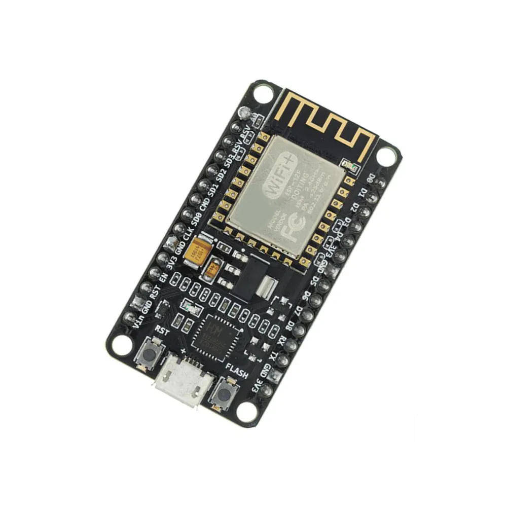
About the ESP8266 microcontroller
The ESP8266 NodeMCU V2 is a powerful microcontroller for IoT and wireless applications. Built on the reliable ESP12E module, it features 17 versatile GPIO pins supporting I2C, UART, PWM, and more. With an onboard CP2102 USB driver chip, it ensures stable USB communication, making it ideal for prototyping and advanced projects.
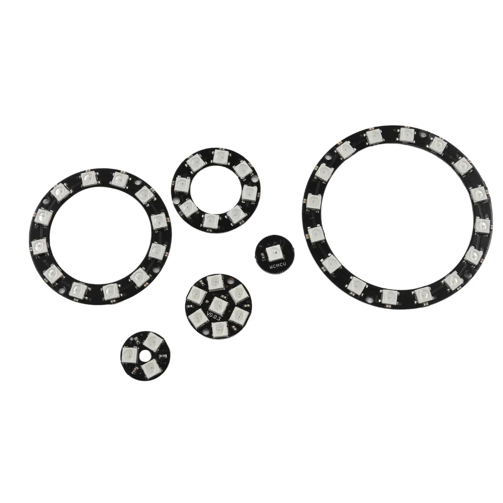
About the Addressable WS2812 5050 RGB Neopixel Rings
WS2812 5050 RGB NeoPixel Rings combine vibrant RGB LEDs with integrated drivers in a compact design. Each LED is addressable, enabling individual control of colour and brightness for stunning lighting effects. With millions of colour combinations available, these rings are perfect for creative projects, from wearables to custom displays and interactive designs. These are available from 1 bit to as high as 32, with the ‘bit’ being the number of less. For example, 1 bit = 1 LED, 16 bit = 16 LEDs.
In this tutorial we are using the 16 bit module. Note: The WS2812B modules come unsoldered and will require to be soldered.
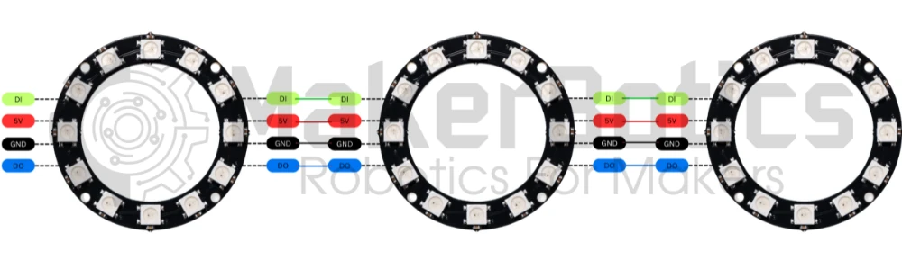
The LED Ring Modules can be daisy-chained to expand the modules as shown below. Simply link the power, Data In (DI) and Data Out (DO) pins from one LED module to another.
Power Connection Pins:
Wire the 5V pin to the ESP8266’s Vin pin. Connect the GND pin to an available GND pin on the ESP8266.
Communication Pins:
Wire the DI (Data In) pin of the LED ring to pin D6. You don’t have to wire the DO (Data Out) pin to the ESP8266. The DO pins are used to activate another set of led modules via signal output.
The image below shows the wiring diagram for the ESP8266 and the WCMCU-2812B-16 LED ring.

It is highly recommended to use the NodeMCU V2 Shield for ease of wiring. Simply wire the LED ring wires into the screw terminal points
Libraries and Setup
The library needed to operate the LED ring is the Adafruit NeoPixel library by Adafruit. This can be downloaded here.
Install the library and then copy and paste the code in the Code section below in the new IDE tab of the Arduino IDE.
Board Selection
There is a list of many ESP8266-based microcontrollers supported in the Arduino IDE. Select Generic ESP8266 as shown below.
Code
Note: As we are using a 16 bit microcontroller module the #define LED_COUNT line (line #10) specifies the LED COUNT to be 16. If you are using a module that has 12 LEDs change the line to #define LED_COUNT 16.16 ff
/*
# AUTHOR: Nisheli P For MakerBotics
# VERSION: 1
# PURPOSE: Flashing individual LEDs in a neopixel ring
# License details: Attribution-ShareAlike 4.0 International CC BY-SA 4.0 Deed
*/
End Result
After successfully wiring the setup and running the code on the Arduino IDE, the LED ring should light up like the one below. The LEDs will change colour in a circular pattern and cycle through each LED.
Downloadable Content
Please find this tutorial’s code on our GitHub page.
Credits
- Maker Community
- The Esp8266 Community
- The STEM Community
- Adafruit Industries