Micro:Bit: Detect Drawing Tutorial
Tutorial Aim:
The aim of this tutorial is to demonstrate how to detect black markings on a white or light-colored piece of paper using a micro:bit and an infrared (IR) sensor, and provide visual feedback by displaying a tick (✓) on the micro:bit’s LED screen when black markings are detected and a cross (X) when they are not detected. This project introduces how to use an IR sensor for reflective color detection by distinguishing between dark and light surfaces based on reflected infrared light intensity.
Requirements:
This tutorial makes use of the Micro:bit Electronics Learning Package.
Pin Layout:
| Micro:Bit Pins: | Infrared MH Sensor Pins: |
| GND | GND |
| 3.3V | VCC |
| 0 | OUT |
Setup:
Please refer to the diagram below for wiring. Please note that the circuit diagram uses a different Micro:bit shield than the supplied in our package, despite this, the wiring is the same.
- Connect the infrared MH sensor to pin 0 on the Micro:Bit using the FM jumper wires
- Open Microsoft Makecode
- Plug in the Micro:bit to the computer

Code Walk Through:
Determining if the sensor detects a drawing:
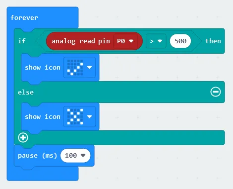
The infrared sensor when detecting black will output high analog values ( > 500), and low analog values ( ≤ 500) when detecting white. Using this we can determine if the infrared sensor has detected any dark/black drawings. The code is paused in-between iterations so that the LED grid has enough time to display the yes/no message. The code for this section will go inside the ‘forever’ block.
- Creating drawing detection conditions: In the Logic tab select the “if-else” conditional block.
- Determining if a drawing was detected: In the Logic tab select the comparison block “0 > 0” and change it to “analog read pin P0 > 500” (found under the Advanced section in the Pins tab).
- Displaying a tick when a drawing is detected: In the Basic tab select “show icon” & use the dropdown box to select the tick (also labeled yes). Place the code line inside the conditional block underneath the if statement.
- Displaying a cross when a drawing was not detected: In the Basic tab select “show icon” & use the dropdown box to select the cross (also labeled no). Place the code line inside the conditional block underneath the else statement.
- Pausing the code: In the Basic tab select “pause (ms)” and set it to 100.
Flashing the code onto the Micro:Bit:
- Make sure the Micro:Bit is connected to the computer
- On the bottom left corner, click the “Download” button and follow the prompts
Python Code:
Entire python code for the tutorial:
Simulated Micro:Bit Display:
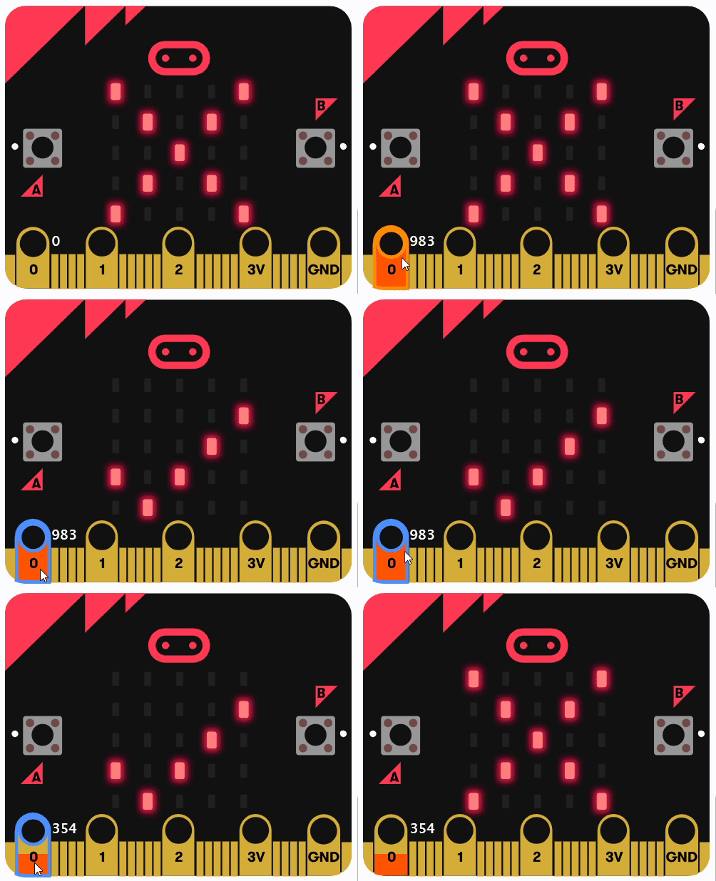
Displaying the micro:bit's LED grid for different analogue values
Results
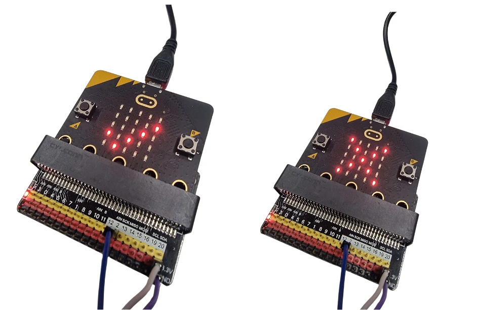
When you move the sensor from a white surface to a black surface—for example, by placing black tape on a white sheet of paper—the sensor will detect the surface color. It will show a tick mark (✓) when over the black surface and display an X when over the white surface.
Downloadable Content:
Please find this tutorial's python & hex file for microsoft makecode on our GitHub.
Credits:
- Microsoft
- The Micro:bit Community
- The STEM Community